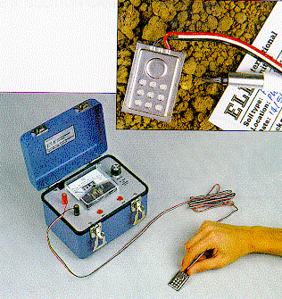
Figure 8: Soil moisture cell and meter unit

The principle of the electrical resistance cell is based on a change in electrical resistance of a porous material owing to variations in moisture content. The cells selected for the York project site (Fig. 8) comprise two plates separated by a processed glassfibre binding which provides the electrical coupling. The cells are approximately 25 by 38 by 3mm in size, and stainless steel corrosion resistance plates are used in their construction. A small thermistor included within the body of the cell enables changes in soil temperature to be monitored. The resistance of the thermistor in the cell is accurate to 1%; cell uniformity with regard to moisture-resistance relations are not however guaranteed. Each cell is connected to a three wire conductor cable that is approximately 9.5m long. The resistance of such a cable probably exceeds 1 megohm; however, no significant corrections need to be made at measured cell resistances of less than 50 000 ohms (Anon 1990).
Each cell has to be inserted carefully into the material which it is to monitor to ensure intimate contact between it and the surrounding material. The characteristics of the material to be monitored should be determined to assess the reliability of any monitoring data recovered. For example, soils with a shrink-swell capacity cause contact problems between the cell and soil, and a saline environment may cause data interpretation problems. Aggressive soil conditions can lead to cell deterioration and loss of data.
The resistance (in ohms) and temperature (in degrees centigrade) of the cells can be obtained manually by connecting each cell in turn to a portable meter device. Alternatively each cell is connected to a datalogger, programmed to record readings automatically on a fixed time frequency.
Left permanently at the project site, the dataloggers are small, rugged and have a internal ten-year lifespan lithium battery. They have an internal temperature sensor which monitors surrounding air temperature, plus seven channels to monitor either resistance or temperature from the cells. Set to record at 30 minute intervals, the memory capacity of the datalogger permits 80 days of continuous monitoring. To retrieve and view the data, each datalogger has to be connected to a personal computer and the appropriate software run.
© Author(s). Content published prior to 2013 is not covered by CC-BY licence and requests for reproduction should usually go to the copyright holder
(in most cases, the author(s)). For citation / fair-dealing purposes, please attribute the author(s), the title of the work,
the Internet Archaeology journal and the relevant URL/DOI. Last updated: Thur Feb 28 2002Dataloggers