Distribution maps of various activity and status categories were created using ArcMAP, a component of ArcGIS 8.0. Distribution plots of the quantities of artefacts, classified on the basis of the various applied interpretative categories (see tables, Figures 10 and 11), provide a means of showing where particular gender groups or activities may have been present in the past.
To create these distribution plots in ArcGIS, image files of the fortress buildings, excavation trenches etc were included as new layers in the map of the site. Tabular summary data from the DBase IV files were then added and the XY coordinates they contained were used to plot the quantitative summary of the desired functional and/or gender category. Plots were designed using the 'Symbology' menu in the 'Properties' dialogue box of ArcGIS. Several different plot types were used, but by far the most effective for pattern-searching were pie-charts, the diameters of which were scaled to the sum of classificatory fields used in their calculation. Pie-charts allowed the distribution and relative quantity of artefacts in several interpretative categories to be visualised simultaneously. This was a useful means of searching for general distribution patterns, the details of which could then be investigated by generating individual category plots for any given artefact category.
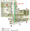
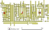
The distribution of artefacts in specific buildings and rooms could also be investigated by zooming into desired parts of the GIS maps. However, it should be noted that the pie-charts plotted to the centre-point of each trench, using the arbitrary coordinates assigned to them as discussed above. Data plotted at a single point, therefore, summarised the artefacts found in a potentially large area of the site. Spatial accuracy of the artefact plots depended on the length of the excavation trench area and its location. Some of the trenches traversed large areas of the site and several buildings, while others were confined to specific rooms or buildings. Trench 750, for example, traverses the west side of Building F, the via principalis, and the whole west side of the palace. However, about two-thirds of it is located in palace P. Its artefacts, of which there were many, therefore plot to the palace P but the potentially wider distribution must be borne in mind when analysing the distribution pattern (Figure 20). On the other hand, the trenches in Buildings A, B and G, and tribune houses K-M, are limited to these buildings and so provide a more reliable distribution pattern (Figure 21). So, while the GIS programme produced effective visualisation of the artefact data, its interpretation demanded careful consideration of the potential living spaces that the artefacts came from.

Figure 20: Sample of GIS view of long trench, Trench 750, through Buildings P and F

Figure 21: Sample of GIS view of short trenches in Buildings K, J and M
© Internet Archaeology
URL: http://intarch.ac.uk/journal/issue17/4/7.3.html
Last updated: Mon Apr 4 2005