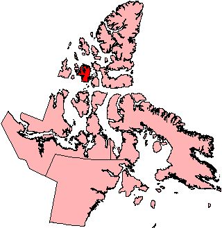
Figure 1: Map showing the location of the Deblicquy Site (QiLe-1) on Bathurst Island, in the Canadian Arctic archipelago
During the summer of 1994, Dawson and a team of archaeologists from the University of Calgary constructed accurate maps of 23 whalebone houses at the Deblicquy site (QiLe-1), an exceptionally well-preserved Thule archaeological site on Bathurst Island, Nunavut (Fig. 1) (Dawson 1998; Dawson 2001).

Figure 1: Map showing the location of the Deblicquy Site (QiLe-1) on Bathurst Island, in the Canadian Arctic archipelago
The objective of this project was to collect detailed architectural information from the surface of the site that could be used to explore how these houses had been constructed. A grid consisting of 3m 3m units was placed over each house mound. The architectural components of each grid unit were then measured carefully and drawn to scale (Fig. 2).
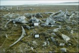
Figure 2: Recording the architecture of House 8 using a 3m grid system
Upon returning from the field, the architectural plans were digitised using AutoCAD software. Because elements such as mandibles, maxillae, ribs, and crania likely had specific architectural functions, they were assigned to different layers in AutoCAD. This resulted in a set of 2-dimensional plans for each house in which whalebones could be selectively 'displayed' or 'hidden', thereby helping to clarify the architectural purpose of each element (Fig. 3).
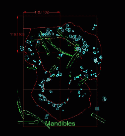
Figure 3: Animated GIF of an AutoCAD plan of House 8. For more detail, click the thumbnail.
While this produced satisfactory results, the 2-dimensional aspect of these plans limited the ability to visualise how each roof frame worked in three dimensions and how symbolic information might have been conveyed to their occupants. It became obvious that the only way to explore this issue was to attempt to actually build one – but in virtual reality.
Laser scanning played a critical role in this next stage of the project. In the interest of creating an accurate model, a CYRAX2500 laser scanner was used to scan a North Atlantic Right Whale skeleton (Eubalaena glacialis) on display at the New England Aquarium in Boston, MA (Fig. 4).
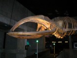
Figure 4: The North Atlantic Right Whale skeleton on display at the New England Aquarium, Boston, MA
While the North Atlantic Right Whale is smaller than the Bowhead whales (Balaena mysticetus) used by Thule groups, its skeletal morphology is similar in all major characteristics (Savelle 1997). Most importantly, the specimen at the New England Aquarium was positioned in a prominent location in the main circulation space, offering line of sight access to the skeleton from all sides.
Of the laser scanners commercially available, the CYRAX2500 offers good accuracy (5mm) at ranges of 50m, which is appropriate for scanning an object as large and complex as a whale skeleton. The next critical issue was determining the spacing of the laser measurement points acquired by the scanner. As the objectives of this project required the capture of the general form of the object, and not the cracks and blemishes of the skeleton, a point separation of 1–1.5mm was used. The skeleton was scanned from a variety of positions in order to minimise the occlusion of elements by other elements. Each of these scan views (front, back, top, bottom, left, right) was then assembled to produce a single array or 3-D point cloud of the object.
In the next phase of the project, these points were converted into an optimised mesh using an engineering software application called Polyworks. An automated process in Polyworks repairs the small holes resulting from situations in which data are missing because of the occlusion of one element by another. From this process we were able to produce a 3-dimensional digital model of the whale skeleton (Movie 1).
Wire frame models of each whalebone element were extracted, and then optimised, coloured, textured, and scaled to the size of intact whalebones mapped and measured at the Deblicquy site. With the AutoCAD map of one of the largest and best-preserved houses serving as a template, the 3-dimensional elements were then used to construct a prototype model (see Figure 3).
The house chosen for reconstruction (House 8) was unexcavated and consists of two rooms or lobes. The largest lobe likely functioned as a family living area, while the smaller one probably served as a kitchen. The most unique architectural feature of this dwelling is the placement of three whale skulls over the entrance passage (see Figures 2 and 3). While planning the reconstruction, a decision was made to leave the premaxillae/maxillae connected to the cranium. The broad base of the cranium, coupled with the projecting arch of the fused maxillae, creates a natural tripod that can be used to support other elements in the roof framework. Using the positions of collapsed mandibles on the AutoCAD map as a guide, we then experimented with different roofing solutions. The most economical solution involved the erection of two self-supporting domes of whalebone over each lobe. These lobes were then connected via a mandible that would have served as a ridgepole. Without this ridgepole, the combined weight of sod and snow would have caused the hide covering to sag, potentially destroying its integrity. The ridgepole was fastened to the apex of each dome. Ribs were then lashed to the roof frame where they were used as structural braces. Ribs were also used to construct a low roof that enclosed the entrance passage.
Once the roof frame was completed, a flagstone floor and elevated sleeping platform were built using virtual rocks whose shapes and sizes were determined using actual rocks measured from the site. The approximate location of the sleeping platform was determined during the 1994 field season where it was partially visible in the house pit. Finally, the house was enclosed using a mesh that was textured to simulate the appearance of hide and sod. Once completed, the model was placed into a non-immersive virtual world so that it could be visually explored in real time under appropriate lighting conditions. Movie 2 provides a video flyby of the exterior of the completed model, and Figure 5 is an interactive view (QTVR) of the interior of the dwelling.
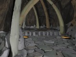
Figure 5: Interactive view (.mov) of the interior of House 8. Click to download.
© Internet Archaeology/Author(s)
University of York legal statements | Terms and Conditions
| File last updated: Wed Sept 27 2005